Guidelines for abandonment of mineral drillholes
Guidelines for Environmental Management in Exploration and Mining
Contents
- 1.1 Background
- 1.2 Application of guidelines
- 1.3 Why are the guidelines needed?
- 1.4 Information
- 1.4.1 Information on construction requirements for water bores
- 1.4.2 Information on abandoning unconventional oil and gas drillholes
2. Materials used to seal abandoned drillholes
- 2.1 Grout plugs
- 2.1.1 Cement grout plugs
- 2.1.2 Bentonite grout plugs
- 2.2 Grouting
- 2.2.1 Mixing grout
- 2.2.2 Placing grout
- 2.3 Backfill
- 2.4 Bridges
3. Materials and guidelines used to seal abandoned unconventional oil and gas drillholes
4. General considerations for drillhole abandonment
- 4.1 Obstructions
- 4.2 Flowing drillholes
- 4.3 Drill site markers
- 4.4 Drillholes left open at landowner's request
5. Sealing abandoned mineral drillholes
- 5.1 Unconfined aquifers
- 5.1.1 Sealing non-flowing drillholes in unconfined aquifers
- 5.1.2 Sealing flowing drillholes in unconfined aquifers
- 5.2. Confined aquifers
- 5.2.1 Sealing drillholes in single confined aquifers
- 5.3 Multiple aquifer systems
- 5.3.1 Sealing drillholes in multiple aquifer systems
6. Sealing abandoned unconventional oil and gas drillholes
- 7.1 Palaeozoic basement
- 7.2 Basement overlain by alluvium
- 7.3 Deep leads
- 7.4 Tertiary sedimentary basins
- 7.5 Superposed basalt flows
Introduction
1.1 Background
- Mineral exploration and mining activities conducted under the Mineral Resources Development Act 1990 may involve drilling holes, in order to:
- obtain samples of earth materials for mineral identification and assay,
- conduct in situ tests (e.g. downhole geophysical wireline logging),
- obtain water samples and monitor groundwater, or
- dewater mine sites.
- Poor drilling practices can result in groundwater misuse, wastage or degradation from flowing bores, or exchange of waters from different aquifers via drillholes. Ingress of materials and surface water directly down drillholes can also cause groundwater pollution.
- The guidelines for abandonment of mineral drillholes ("the guidelines") have been developed to protect Victoria's groundwater resources from any detrimental effect that may result from mineral exploration and mine development drilling. The guidelines are in keeping with the general philosophy of resource management and protection embodied in the Water Act 1989 and the Environment Protection Act 1970.
The term "drillhole" as used in the guidelines includes all holes drilled by drilling rigs. It does not apply to other excavations such as backhoe pits, shafts, and drives. A drillhole is deemed to be "abandoned" after it has been drilled to total depth and any initial sampling and testing is completed.
Once these activities have been completed the drillhole should be abandoned in accordance with these guidelines. Normally, abandonment procedures would be carried out immediately following drilling and testing while the drilling rig is positioned over the drillhole.
The guidelines are concerned with adequate sealing of abandoned mineral drillholes. The principal objective of sealing abandoned drillholes is to restore as far as possible the original hydrogeological conditions.
- Abandoned drillholes need to be sealed properly to:
- prevent pollution of groundwater by the entry of poor quality water and other foreign substances down the drillhole.
- eliminate any physical hazard which may result from an open hole in the ground.
- prevent intermingling of waters from different aquifers via the drillhole.
- conserve aquifer yield, ie. stop groundwater flowing to waste.
1.2 Application of guidelines
- The guidelines provide advice to licensees under the Mineral Resources Development Act 1990 on the abandonment of mineral drillholes. They apply to all mineral exploration and mine development drillholes, drilled on both exploration and mining licences.
- The guidelines refer to "standard licence conditions" which must be complied with. The "standard licence conditions" are those which routinely apply to Exploration Licences. However, they may be varied for particular exploration licences and may be should check the licence to establish the conditions which apply.
The guidelines do not cover bores drilled by exploration or mining companies specifically for water supply, drainage, dewatering purposes or for groundwater monitoring. Such "water" drilling by mineral exploration and mining companies falls under the Water Act 1989.
Standard licence conditions require that the drilling, construction, or abandonment of bores drilled for these purposes be undertaken in accordance with the Water Act 1989. Drillholes drilled for purposes other than "water" but subsequently converted for such uses also come under the Water Act 1989.
1.3 Why are the guidelines needed?
The Water Act 1989 provides protection for groundwater in situations where "water" is the primary objective of the drilling. Regional water authorities are responsible for administering those parts of the Water Act 1989 pertaining to groundwater extraction, drilling and construction of bores, and licensing of drillers.
However, mineral exploration and mine development drillholes which are subsequently abandoned are not subject to the Water Act 1989.
- The Environment Protection Act 1970, provides the legislative framework for protecting groundwater from pollution, but does not cover abandonment of mineral exploration and mine development drillholes.
- The guidelines have therefore been developed by the department to provide technical advice as to the practices which should be adopted when abandoning mineral exploration and mine development drillholes, drilled by licensees under the Mineral Resources Development Act 1990.
1.4 Information
When deciding on the methods of abandonment to be used to seal drillholes it is necessary to have some understanding of the site characteristics.
Factors to be considered include:
- Site geology – stratigraphy, rock types and degree of consolidation etc.
- Site hydrogeology – number and types (confined and unconfined) of aquifers, confining bed characteristics (lithology, thickness, etc).
- Groundwater occurrence – groundwater pressure levels (water table or potentiometric surface level), water chemistry and quality.
- Site topography – likelihood of surface waters flooding into drillholes.
Information on groundwater systems at particular locations can be obtained from regional water authorities geologists, who can provide advice on expected groundwater conditions at drill sites. (For contact information, see 7)
1.4.1 Information on construction requirements for water bores
Regional water authority drilling inspectors can provide technical advice on drilling and sealing methods. (For contact information, see 7)
- Minimum construction requirements for water bores in Australia, 3E, ADITC (Feb 2012).
- Groundwater and wells by F G Driscoll, published by Johnson Filtration Systems Inc., St Paul, Minnesota (1986).
- Drillers training and reference manual published by the National Water Well and Drilling Association of Australia (1982).
1.4.2 Information on abandoning unconventional oil and gas drillholes
Information on abandoning unconventional oil and gas (coal seam gas, oil shale, shale oil, etc) drillholes can also be obtained from the following references:
- Code of Practice For the construction and abandonment of petroleum wells and associated bores in Queensland Petroleum and Gas Inspectorate Version 2, 16 December 2019, Department of Natural Resources, Mines and Energy, (DNRME).
- API Bulletin E3 (BUL E3): Environmental guidance document: Well abandonment and inactive well practices for U.S. exploration and production operations 2E (April 1, 2018).
2. Materials used to seal abandoned mineral drillholes
2.1 Grout plugs
- Grout plugs are used to prevent intermingling of groundwaters from different aquifers intersected by mineral drillholes and flow from the drillholes. Drillholes can be sealed by completely infilling with grout or by setting grout plugs at predetermined positions in the hole.
Grout generally consists of a fluid mixture of cement and water (neat cement). However, the slurry may also contain sand, gravel, bentonite or hydrated lime.
A clay slurry made with high-grade bentonite can also be used provided that it is not emplaced at or near the ground surface where drying and shrinkage of the grout will occur, or where water movement will wash away the clay particles.
Synthetic materials, especially polymers, are also used as grouting materials, but their extremely low solids content and substantial shrinkage when dried make them less suitable for sealing drillholes than the other grout types.
- Low viscosity (high fluidity) grouts are used to plug fine-grained, low permeability unconsolidated rocks, whereas high-viscosity grouts are used for coarse-grained, highly permeable unconsolidated rocks, cavernous rocks and fractured rocks.
2.1.1 Cement grout plugs
- Regular cement or rapid-hardening variations are generally the preferred grout for plugging mineral drillholes. All cementing should be carried out using only mix densities approved by the manufacturer for the conditions of use.
- The cement grout mixtures should just be fluid enough to flow through grout pipes. It is better to have a drier rather than wetter mixture. Water used in mixing cement grout should be free of oil and other organic material such as plants, leaves and fragments of wood. The salinity of the water should be less than 2000 mg/L Total Dissolved Solids (TDS). High sulphate content is particularly undesirable.
- Sand or other bulky material can be added to the cement slurry to enable the grout to bridge larger openings without excessive fluid loss and/or to reduce the cost of material where large volumes of filling material are required. The coarse materials add to the difficulty of handling and placing grout.
- Bentonite clay can be added to the cement to hold the cement particles in suspension, reduce shrinkage, and improve fluidity of the slurry. However, the amount of bentonite added should not exceed 6% otherwise shrinkage of the cement will occur. It is best to mix the bentonite and water first, then add cement to the clay-water suspension.
2.1.2 Bentonite grout plugs
- Bentonite (essentially montmorillonite) is also used as a grouting material because of its relative ease of placement. Commercial bentonite is available in pelletised, granular and powdered form. The pelletised and granular forms are both suitable for grouting drillholes.
Bentonite grout has advantages over cement grout. It has a faster setting time and it adheres to both soil and casing. However, bentonite should not be used within 2m of the ground surface because it will dry out and shrink.
Furthermore, the presence of saline water (greater than 2500 mg/L TDS) causes bentonite grout to flocculate which reduces its viscosity, and organic acids can destroy the impervious character of bentonite grout.
- Bentonite grout has low shear strength and density. It should therefore not be used in high pressure aquifers.
- Bentonite grout should be carefully prepared, as too much water forms liquid slurries that are unsuitable for sealing drillholes, and too little water results in a grout that shrinks when emplaced in drillholes even if the surrounding ground is moist.
- Granular bentonite should be mixed gently into the water with a paddle, not a mixer or pump as these latter methods break up the particles and cause the viscosity of the slurry to increase permanently.
When mixed with water, bentonite hydrates very rapidly making it difficult to place the granular form by dropping the particles into small spaces. Pellets dumped down small drillholes may begin to stick together within less than a metre of the surface and may bridge above the intended depth setting.
In general, pellets should always be tamped into place to eliminate any bridging that may have occurred.
A better practice is to use a bentonite slurry consisting of granular bentonite and pump it down the drillhole via a grout or tremie pipe. Care needs to be taken when preparing bentonite mixtures that are to be pumped into drillholes.
The maximum viscosity of bentonite grout that can be pumped is formed from a mixture of 300L of water per 40kg bag of bentonite. Unfortunately, after emplacement, grout with this concentration of bentonite may eventually shrink 25%, even if the ground around the grout is moist.
Virtually no shrinkage of bentonite grout will occur if it is mixed at concentrations of 220L of water per 40kg bag of bentonite. It should be noted that grout of this concentration can be pumped only if the water has been pretreated with 0.5L of polymer per 220L.
The polymer prevents the clays from hydrating immediately, and once the particles are evenly distributed in the water the viscosity remains low enough for the slurry to be pumped for about 20 minutes.
2.2 Grouting
2.2.1 Mixing grout
- Grout should be mixed thoroughly and be free of lumps. Grout should be mixed in batches so that it can be emplaced in drillholes before it sets.
- Equipment for mixing and placing grout need not be elaborate. However, as the chemical reactions that cause grout to set begin as soon as the slurry is prepared, the equipment to mix the grout must be adequate to enable the grout to be emplaced in the drillhole while it is still fluid.
- The volume of grout required can be estimated by calculating the volume of drillhole to be grouted (based on the drillhole diameter and length to be grouted). However, the volume required cannot be determined accurately due to possible irregularities in the size of the drillhole and possible losses of grout into formations, particularly into fractured and cavernous rocks.
2.2.2 Placing grout
- In order to ensure that grout will provide an effective seal it should be emplaced in one continuous operation before the initial set of the grout occurs.
- Grout should be introduced at the bottom of the zone to be sealed to ensure that no gaps are left in the grouted interval due to bridging in the drillhole, and to prevent segregation and contamination of the slurry. This is particularly crucial when grouting below the water level to prevent excessive dilution of the grout.
- If the hole has been drilled by the rotary method and is filled with drilling mud, the grout pipe can be lowered to the desired grouting depth through the mud. When the grout is introduced, the mud will be forced upward on the grout because the grout is the heavier (denser) fluid.
- Where temporary casing is used to prevent caving, grout can be introduced into the drillhole down the casing, but the casing should be pulled while the grout is still fluid so that the grout will closely contact the wall of the hole. When the casing has been completely removed, the drillhole should be topped-up with grout.
- Small diameter pipe, eg. grout or tremie pipes of 50mm (2") to 100mm (4") diameter, can be used to conduct the required quantity of grout in the drillhole. The grout pipe should be held slightly above the setting position i.e. the bottom of the hole, top of bridge or the top of backfill. The bottom of the pipe should always be positioned below the surface of the slurry during grouting.
- The grout slurry may be gravity fed into drillholes less than 20m deep. Pumping is the only practical means of introducing grout when deep seal settings are required. Pumping enables large volumes of grout to be introduced rapidly and forced into the space to be sealed with little chance of leaving voids in the grout.
2.3 Backfill
- Backfilling refers to the process of filling drillholes to pre-determined depths with either material removed during drilling, or with purpose bought sand.
Sand for backfilling should be fine enough so that cement will not penetrate more than 50mm to 75mm (2" to 3") into the surrounding formation. Material sold as plaster sand or mortar is usually satisfactory.
More than half the sand should be of grain sizes between 0.3mm (0.012") and 0.65mm (0.025") which is about the coarsest material that will retain grout slurry if grout is to be set on top of the backfill.
2.4 Bridges
A bridge is a solid fixture that is positioned in a drillhole to form a base for grout or backfill material, when the drillhole is to be only partially infilled. Bridges can be made from wooden plugs or metal plates.
Cementing baskets, formation packers and, in some cases, hessian bags can also be used as bridges.
3. Materials and guidelines used to seal abandoned unconventional oil and gas drillholes
For the construction and abandonment of unconventional oil and gas well guidelines (coal seam gas, oil shale, shale oil, etc), see the code of practices and guidelines developed by the Queensland Department of Natural Resources and Mines (DNRM) referenced in Section 1.4.2.
4. General considerations for drillhole abandonment
4.1 Obstructions
Before sealing, drillholes should be checked to ensure that there are no obstructions that may interfere with effective sealing operations. Where possible, all obstructions should be removed from the drillhole prior to sealing.
4.2 Flowing drillholes
- Groundwater discharge from flowing bores has to be controlled before sealing. Flow can be controlled by introducing high specific gravity fluids (e.g. barite weighted drilling mud) to stop the flow, or by pumping the drillhole itself or nearby bores to create a drawdown cone in the drillhole to be abandoned.
- Cement grout should be used exclusively in drillholes that flow and/or where the groundwater head of a confined aquifer is above the top of the aquifer zone.
- The length of grout plugs set in flowing drillholes should be sufficient to completely stop discharge of groundwater.
- If groundwater flow cannot readily be controlled the department should be notified immediately. The department will liaise with appropriate technical experts and provide direction to the licensee for controlling the flow and sealing the drillholes.
4.3 Drill site markers
- In some instances licensees may wish to re-access drillholes for additional sampling and testing. Methods of site identification will depend on land use constraints. Licensees are advised to determine accurately the coordinates of all drillholes to facilitate their relocation if required.
- Temporary surface markers such as wooden pegs, metal poles, etc should only be used where they will not interfere with other land uses.
- Where land use precludes surface markers, metal plates can be set below the soil fill e.g. level of cultivation, to facilitate re-locating the drillhole using a metal detector. A temporary marker can be placed nearby where it is unlikely to be disturbed e.g. along a fence line or adjacent to a tree.
- Landowners should be consulted before positioning temporary site markers.
- Surface site markers should be removed at the completion of the drilling program unless the sites are to be re-accessed during the period of the licence. All surface markers should be removed at, or before, the termination of the licence.
4.4 Drillholes left open at landowners request
Where a landowner requests that a drillhole be left open for water supply purposes, the hole must be licensed by the regional water authority.
This will require a copy of the drill log (confidential information may be deleted) and any available details of groundwater such as depth struck, water quality, etc.
- Licensees should obtain written confirmation from the landowner that the bore has been licensed.
5. Sealing abandoned mineral drillholes
The following provides general guidelines on sealing abandoned drillholes in commonly encountered hydrogeological settings. Where local circumstances preclude the use of the described methods, and subject to approval by the Inspector of Mines, other methods may be acceptable.
- Standard licence conditions require that drillholes are capped below ground surface and that major aquifers intersected downhole are sealed off. In the case of wide diameter drilling, by bucket auger (or Calweld) equipment, drillholes must be backfilled.
- Surface caps can consist of either grout plugs, bridges, casing caps or backfill. Standard licence conditions require that the top of the grout, bridge, casing cap or any casing remaining in the drillhole be a minimum depth of 300mm below ground surface and the void above the grout, bridge, casing cap or casing be backfilled with soil.
- Where the ground is likely to be ploughed or graded, the cap may have to be placed or the casing cut at a depth greater than 300mm. The landowner should be consulted as to the appropriate depth.
- The soil backfill should be compacted and mounded over the hole to prevent ponding of surface water above the drillhole and to allow for possible later subsidence.
Where it is anticipated that the drillhole will need to be re-entered for deepening and/or further testing, temporary plugs consisting of easily drillable material (such as weak cement) can be used to seal the hole.
If bridges are used down hole they should also be of drillable material such as wooden plugs, PVC, etc. On completion, or at the termination of the licence, the drillhole should be permanently sealed as per the methods given below.
5.1 Unconfined aquifers
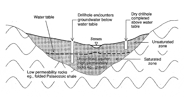
An unconfined aquifer (also referred to as a water table aquifer) is permeable rock that extends from the land surface down to a relatively impermeable base (Figure 1). It is generally only partially filled with water.
The top of the zone of saturation, referred to as the water table, is the level at which the water will be encountered in drillholes. Water does not rise up the drillhole above this level. In Victoria the water table is rarely more than 50m deep and in some places it is at or close to the land surface.
5.1.1 Sealing non-flowing drillholes in unconfined aquifers
- The main objective in sealing drillholes that intersect only one rock type (provided that groundwater is not flowing from the hole) is to prevent entry of water and objects directly down the drillhole and to remove the surface disturbance hazard.
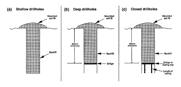
- Non-flowing drillholes in unconfined aquifers can be effectively sealed relatively simply by backfilling with drill cuttings. The fill material should be compacted into the drillhole and soil mounded over the hole (Figure 2a).
- Blockages, due to either side wall collapse or hang-up of the backfill, can occur when attempting to backfill deep drillholes. Although the blockages may serve as temporary bridges which allow backfilling to be achieved, they are liable to later movement which can result in reopening of the drillhole.
- Where it is not practicable to completely backfill drillholes, a bridge can be positioned in uncased drillholes as a base for the backfill (Figure 2b). If the hole is cased, a bridge (e.g. metal plate) cap can be positioned across the top of the casing to stop the backfilling from falling down the hole (Figure 2c). Alternatively, a casing cap can be screwed or glued to the top of the casing.
5.1.2 Sealing flowing drillholes in unconfined aquifers
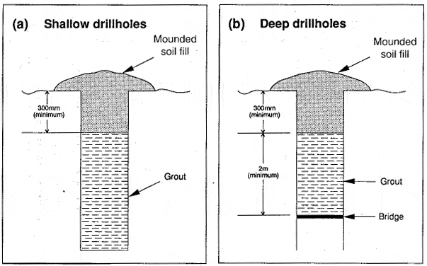
- Groundwater can flow at the surface from drillholes in some unconfined aquifers. Where groundwater flows at the surface, standard licence conditions require that a grout plug at least 2m thick be part of the surface cap to permanently stop flow.
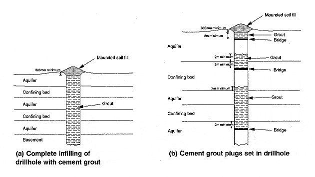
- Shallow drillholes should be completely infilled with grout to within 300mm of the ground surface, and the upper 300mm backfilled with soil (Figure 3a).
- Where complete grouting is not practicable, a bridge can be positioned in the drillhole and a grout plug set above the bridge (Figure 3b).
- Use of casing fitted with a cap is generally not adequate as a surface cap to seal flowing drillholes in unconfined aquifers because groundwater may discharge through the annulus between the casing and the hole wall.
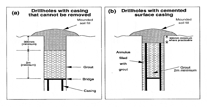
- Where possible, all surface casing which has not been pressure cemented in position should be removed from drillholes to ensure placement of effective seals.
If all the surface casing cannot be removed, at least the upper 2.5m should be cut off and removed. A bridge can then be positioned on top of the remaining casing and a minimum of 2m of grout set above the bridge (Figure 4a).
This procedure will ensure contact of the grout with the wall of the hole which will form a watertight plug.
Surface casing that has been cemented in position can be used as a surface seal provided that the upper portion is infilled with grout (Figure 4b).
5.2 Confined Aquifers
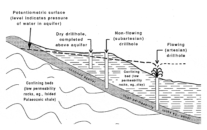
- Confined aquifers occur where permeable earth materials are overlain by less permeable confining beds that retard vertical movement of groundwater (Figure 5).
- Confined aquifers are fully saturated with groundwater. When a confined aquifer is penetrated by a drillhole, water will rise up the drillhole. The water level reflects the pressure of the water in the aquifer. If the pressure is above the ground surface, groundwater will flow freely from the top of the drillhole. Such discharge is referred to as artesian flow.
- In sub-artesian conditions the water level in the drillhole is above the top of the aquifer, but it is below the land surface. Sub-artesian drillholes do not flow at the surface.
- In situations where a permeable stratigraphic layer is overlain by a low permeability layer and is only partially saturated it behaves as an unconfined aquifer and can be abandoned using the methods described in 4.1.1.
5.2.1 Sealing drillholes in single confined aquifers
- The primary objective in sealing drillholes in single confined aquifers is to contain water in the aquifer. This will stop any groundwater discharge from the drillhole.
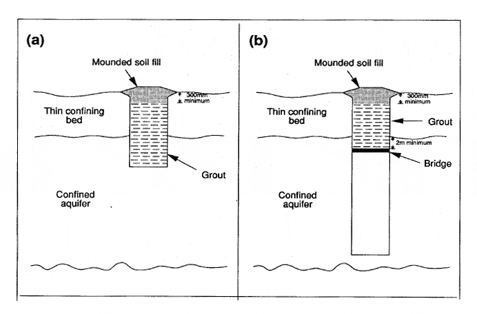
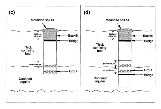
- Options for sealing drillholes that encounter single confined aquifers are depicted in Figure 6. The figure illustrates four different combinations of site hydrogeology (aquifer and confining bed thicknesses) and drillhole depth, together with possible sealing configurations.
Grout plugs should be set above the top of the aquifer (i.e. across the aquifer – confining bed interface). The grout should be a minimum of 4m thick (2m above the interface and 2m below) and should be of sufficient thickness to control the groundwater pressure.
A rough rule of thumb is that 1m of grout is required for every 0.75m of groundwater head above the top of the aquifer. A 10m thick grout plug is sufficient in most circumstances.
Surface caps are required, in addition to plugs set down the drillhole, to remove the physical hazard of an open hole in the ground, to stop water and other objects entering the hole and as an added precaution against groundwater discharge.
If the drillhole is successfully plugged above the top of the confined aquifer, the surface cap does not require any grout (figure 6c and 6d) although use of grout in the surface cap is recommended as an added precaution against groundwater seeping from the drillhole.
5.3 Multiple aquifer systems
- Multiple aquifers are groundwater systems where more than one aquifer is present at a given site. In these systems permeable aquifers are separated by lower permeability confining beds (Figure 7). The groundwater in each of the aquifers may exhibit significantly different pressure regimes and water chemistry.
The pressure in the confined aquifers is normally above the top of the aquifer horizon, and the difference in the pressure regimes can result in intermingling of waters from the different zones via drillholes.
The direction of inter-aquifer groundwater flow depends on the pressure differentials between the aquifers.
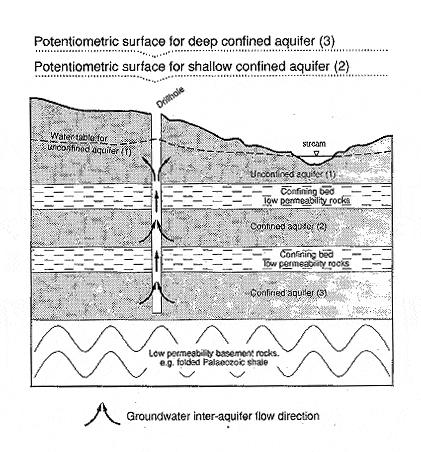
- If the hydrostatic pressure in any of the aquifers is above ground level, drillholes intersecting the aquifer horizon will flow groundwater.
- Multiple aquifer systems are common in Victoria's sedimentary basins and in deep lead situations where permeable alluvial sands and gravels are covered by either basalt or low permeability sediments.
5.3.1 Sealing drillholes in multiple aquifer systems
- Major aquifers intersected in drillholes should be sealed to prevent inter-aquifer flow via the drillhole. It is not necessary to seal individual aquifer sand beds in a sand/clay sequence, however, grout plugs should be positioned between major aquifers.
- Examples of appropriate methods for sealing drillholes that intersect multiple aquifer systems are given in Figures 8 and 9.
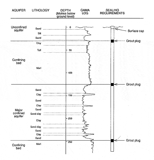
- The simplest method of sealing drillholes in multiple aquifer systems is to grout the entire drillhole with cement. Where this is not practicable because of hole depth, plugs should be positioned at the interfaces between major aquifers and overlying confining beds. The grout should be at least 4m thick, with 2m above and 2m metres below the interface.
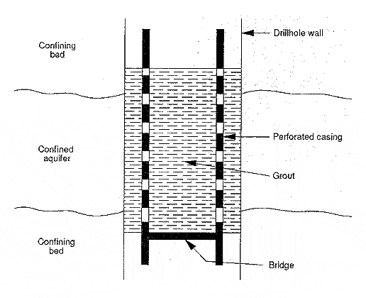
If casing opposite the zone to be sealed has not been cemented in place and cannot be removed, bridges should be positioned inside the casing 2m below the intervals to be sealed off. Holes should be cut into the casing above the plugs with a casing ripper, cutting torch, mills knife, or other type of perforator.
Grout should then be introduced into the casing and forced through the perforations into the annular space between the casing and the wall of the drillhole. This method of sealing is depicted in Figure 10.
6. Sealing abandoned unconventional oil and gas drillholes
For sealing abandoned unconventional oil and gas (coal seam gas, oil shale, shale oil, etc) drillhole guidelines, see:
7. Victorian applications
All the possible combinations of site geology, occurrence of groundwater and groundwater pressure regimes, and suitable abandonment procedures are too numerous to describe in these guidelines.
Geological situations commonly encountered when drilling for minerals in Victoria and appropriate sealing techniques are described below.
7.1 Palaeozoic basement
Palaeozoic basement in Victoria is generally regarded as a single aquifer, requiring only a surface cap. However, flowing drillholes can be encountered in discharge zones.
7.2 Basement overlain by alluvium
In areas where basement rock is overlain by alluvium, a plug should generally be placed across the boundary between the basement and the alluvial deposit in addition to a suitable surface cap.
7.3 Deep leads
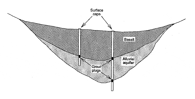
- The term "deep lead" is used here to refer to a buried river channel deposit. It is often covered by basalt, but it can also be buried under other sediments. Deep leads are often sources of good quality groundwater supplies.
- At least one downhole plug is required in drillholes intersecting deep leads in addition to a surface cap. The downhole plug should be placed across the interface between the deep lead deposit and the overlying rock.
- If the drillhole fully penetrates the deep lead into underlying rock, a plug should also be placed across the interface between the deep lead and the underlying rock (Figure 11).
7.4 Tertiary sedimentary basins
Drilling in sedimentary basins, such as the Murray, Otway and Gippsland Basins, commonly intersects multiple geological formations with distinctive hydrogeological characteristics. In these areas it is necessary to isolate aquifers by setting plugs downhole, as per 4.3.1.
7.5 Superposed basalt flows
In basaltic provinces such as the Western Plains of southwestern Victoria and the Keilor-Werribee Plain of south-central Victoria, it is not uncommon for drillholes to intersect several basalt flows separated by sediments or soils developed on the basalt.
These interflow materials generally have different hydrological characteristics than the basalt resulting in a multiple aquifer system. Where reasonably practicable, grout plugs should be positioned at each interface between the different rock types.
8. Records of abandonment procedures
Standard licence conditions require that accurate records are kept of abandonment procedures to provide future reference and to demonstrate to the department that the drillholes have been satisfactorily abandoned.
Details to be provided should include:
- groundwater conditions
- depth sealed
- quantity and type of sealing material used
- casing details
- changes made to the drillhole during abandonment.
In situations where closely spaced drilling has been undertaken in relatively uniform hydrogeological regimes, abandonment documentation is not required for every individual drillhole.
In such situations, generalised descriptions and diagrams will suffice. Sufficient documentation should be provided to demonstrate to the department that adequate abandonment procedures have been followed to protect the local groundwater system.
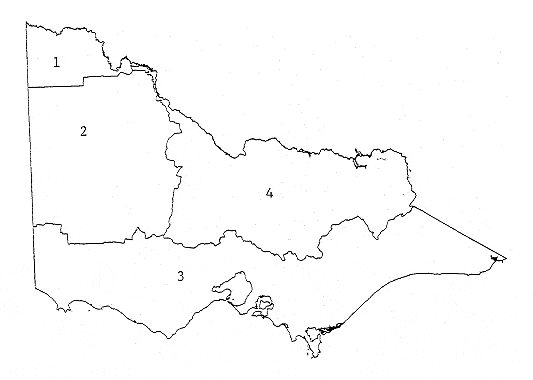
9. Regional water authority contacts
Chief Executive Officer
Sunraysia Rural Water Authority
PO Box 817
Irymple VIC 3498
General Manager
Wimmera-Mallee Rural Water Authority
PO Box 19
Horsham VIC 3400Phone: (03) 5362 0200
Fax: (03) 5382 6192
Chief Executive Officer
Gippsland & Southern Rural Water Authority
PO Box 153
Maffra VIC 3860Phone: (03) 5139 3100
Fax: (03) 5139 3150
General Manager
Goulburn-Murray Rural Water Authority
PO Box 165
Tatura VIC 3616Phone: (03) 5833 5500
Fax: (03) 5833 5509
Page last updated: 08 Jun 2022